To be honest, I really like the idea but I dislike that it is based on a microcontroller faking the components.
It reminds me of a similar experience I had in a museum where the experiment had you cycling to give power to a bulb. The quicker you cycled, the more power you gave to the bulb and the brighter it was. But it was based on some microcontroller and the light bulb’s brightness was not proportional to how fast you cycled. It has like 3 preprogrammed brightness. It completely failed to give kids the intuition of the physics behind the phenomenon.
Anyway, it’s probably an unfair comparison but I like having the real deal when learning or teaching.
In school, I studied digital logic (like, chips and hardware) as much as I studied anything software, but professionally I’ve only written code.
One of the biggest “disappointments” my professors shared - which I’ve never confirmed in industry- is that this is super common for digital logic, or else it’s just a “lookup table” with precomputed outputs for every input.
Wow, really? We have an exhibit like that in the science centre where I live, I’m pretty sure it just uses a car alternator and some headlights though. You can hear the soldering fast and the lights pulse with every power stroke of the pedals.
Does anyone have suggestions as to how to learn about electronics in general - resistors, transistors, all those things that make up even just basic circuit boards which are all magic to me?
When I was about 30 and wanted to scratch the same itch, I found an introductory electronics course being run at my local community college. From distant memory, it definitely covered off resistors, capacitors, coils, Ohm's Law, then worked its way to transistors and I think op amps. Somewhere along the way we got into the basics of creating logic gates, which also served to fill a void I had in my understanding of computers.
At a much younger age, I was interested in amateur radio. As luck would have it, I learned of a night school course being held at one of the local high schools that was meant to teach you everything you needed to know to get your license. The instructor (late 20s, if I had to guess) really knew his stuff. I think this gave me a far better grasp of the relevant electromagnetic and electronics theory and practice than I feel is made available through present-day amateur radio "memorize the answers and some context around them" teaching materials. My point is, if you want to stretch your understanding of electronics, it's possible a local ham might be another good option to consider.
Everybody will probably recommend a bunch of books or MOOCs with varying degrees of practicality but if you want to learn in the sense of building some sort of intuition, then just buy:
- A large breadboard
- A battery holder
- An online kit with an assortment of passive components (resistors, capacitors, inductors)
- A cheap USB oscilloscope
Some of these kits even include things like FETs, opamps, 555 timers etc. Which really stretches what you can build.
Then just look online for circuits that you find interesting, build them and probe them (with the oscilloscope). The closer you get to building something you find useful the more engaging the experience will be.
The Navy Electricity and Electronics Training Series (NEETS) are a good high level overview that can help you learn which areas you want to explore further. Specifically to the questions you asked, module 1 will give you the overview on basic circuits.
I'm sure someone will have a much better recommendation. Do you have an old physics book? Working a few or a lot of simple voltage divider problems, to just really nail down V=IR is helpful. a ton of digital stuff can be thought of as snapshots between two states. might give you some help reading schematics as well.
a pretty ham fisted analogy, imagine a full glass of water on the left, and an empty glass of water on the right. you pour the water from the full glass into the empty glass. There is a BOATLOAD of physics happening there. but all you really care about is Left glass full -> left glass empty. easy peasy.
Stuff that's changing is tougher, like radios or whatever. digital is sort of steady -> chaos -> steady. analog you care a lot about all the little partial derivatives.
The ben eater videos maybe? https://eater.net/8bit/ He'll walk you through a lot of basic electronics in a pretty casual way.
I wish I could give you something more "sure fire way to learn electronics" but my knowledge is pretty haphazard. that stuff helped me.
I was going to recommend Ben Eater's videos and kits as well. I'm not-so-patiently waiting for my oldest kid to be ready to work through those with me.
I know it is targeted at kids, but I think Snap Circuits is pretty great. All the electronic components are attached using what are effectively clothing snaps. But they’re all real electronic components and you can make really interesting things. The books walk you through from very basics to more advanced and help you learn the basics.
I learned from it playing with it with my son!
Take one of those kits for kids, play and experiment. Build your intuition. Then you can go with the theory little by little as needed. I would recommend against going theory first as it is often overwhelming and discouraging.
I did a number of basic electronics tutorials and kits without much of it sticking. Mainly because there wasn't anything very interesting on the other side of the project. What got me through the basics into understanding was, http://www.ic0nstrux.com/design-your-own-video-game-console-... in which you learn how to build simple video game consoles.
Now, resistors, capacitors, transistors and everything else had functions that solved problems I was having.
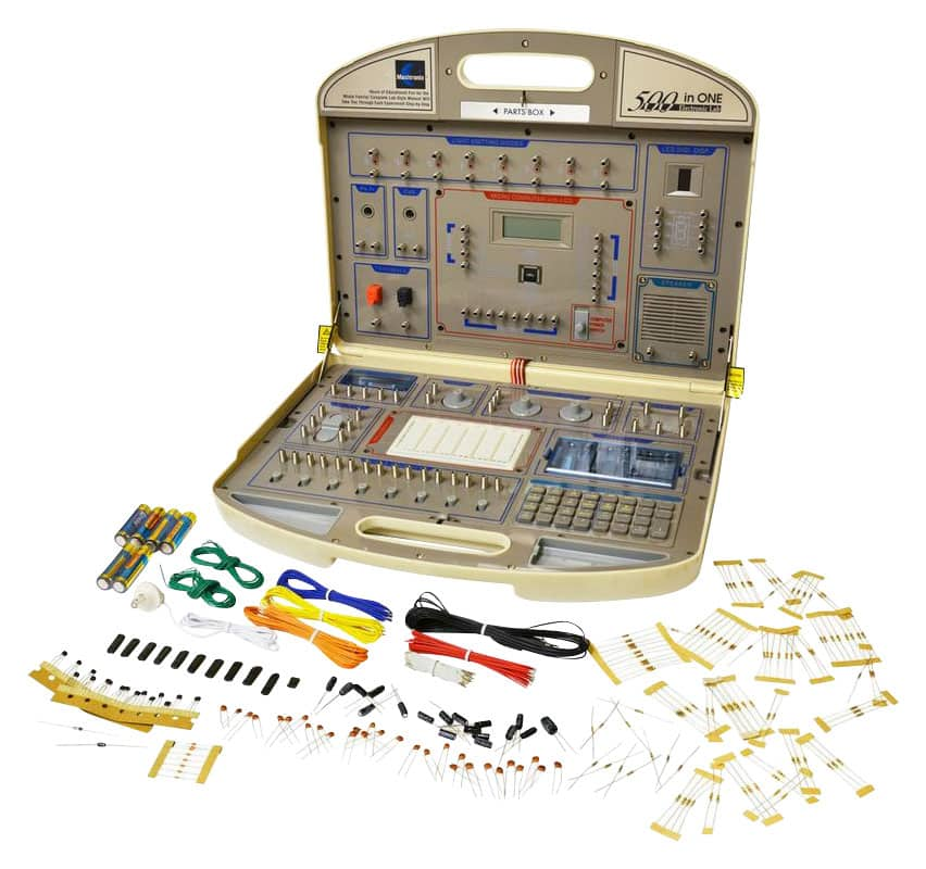
There used to be these massive electronic experiment kits you'd get from like Radioshack during the early 2000s. Like this: [0][1]. I haven't found any all-in-ones with the same depth sold today but maybe someone else has found something.
You can make your own project, with arduino and a bunch of components. There should be a project that will require use of different techniques, like using a transistor instead of a relay, using resistors to not burn up components, using a voltage divider circuit (requires 2 resistors), and other techniques.
I am a beginner, so it would be hard to suggest what project to implement. I mainly used resistors to not burn the arduino I/O pins, and voltage divider circuit to step down the voltage for components with voltage different than 5v.
That book Code, by Charles Petzold, is good. It starts talking about the development of switches and relays, then logic gates, then how to add and subtract with logic gates, build memory from logic gates, then about the first integrated circuits from the mid-1970's, the 8080, and I don't remember what else.
It's more computing focused that electronics focused, but it's a great entrypoint for learning about how logic gates translate into an algorithmic unit and memory.
the sparkfun videos give a pretty good intro to the kinds of parts they sell.
Also, if you're only interested in small hobbyist circuits, it will simplify things if you only think about DC. AC is a rabbit hole of electrical engineering and physics complexity that you may not be interested in quite yet.
Have you tried using a breadboard? That'll give a hands-on experience.
Try the Khan Academy Electronics course if you want to know the science behind the stuff.
I don't understand questions like this. You have the entire internet to search, powerful search tools, libraries, bookstores, etc. You're asking about the most basic building blocks of a subject (akin to asking "How can I learn about arithmetic?"), of which there must be an effectively infinite amount of material aimed at beginners.
The best answer to your question is "Do anything. Anything at all".
Learn maths first, right up to calculus. It'll hurt a lot less and improve your life anyway. You can wire up circuits without knowing much but without maths it's difficult to build anything more than trivial stuff on your own with an objective set out to "I want to solve problem X". Until then you're an assembly worker wobbling on the shoulders of various dubiously designed assemblies put out by people who shouldn't be allowed to do it (Forest Mimms is an example).
Consider a transistor is a voltage-controlled current source (TRANSfer resISTOR) as a model and the head scratching starts.
When I first got into Arduino I bought myself a set of 74xx gates and a breadboard and I wrote a program that would try a range of possible inputs and generate truth tables, I found that the breadboard + 74xx gates + jumper wires was a very physical way to experiment. The range of parts you can get is huge:
even though my understanding now is that you are probably better off using the 54xx CMOS parts instead.
You can do the same with switches and LEDs but boy do you run into trouble when you get into parts like flip-flops that have a memory because you will press a button once and thanks to keybounce your device will think you pressed the button 10 times. You get better results using the Arduino as a driver and those programs are really easy to write.
Hardware denouncing is really easy to implement, you only need a 0.1uF capacitor, an 1k resistor and a 7414 (Schmitt trigger inverter). If your feeling particularly fancy and price is not a concern the LS18 is magical.
That said, I agree that using an MCU is even easier and almost always cheaper if when you choose the appropriate chip.
The Digital Equipment Corporation H-500 Computer Lab made it's appearance around 1969.
Michael Gardi built a reproduction of the H-500 Computer Lab that is nothing less than spectacular. Not only did he pay meticulous attention to detail, but he has also produced clear and engaging documentation. It is not just a beautiful project; it is a work of art!
Michael's goal clearly went beyond building a simple functional equivalent to the H-500. He was equally concerned with maintaining an "outwardly accurate appearance of the original". After 3 months of work he succeeded in every way. You can find details of his work here on Hackaday and in his Instructable.
If you just want to play with digital logic in 2023, there are easier methods. You could just download one of the many free simulators for Windows. De Morgan's theorem is just a few clicks away.
Silicon Zeroes might be up your alley, though IIRC it starts with logic gates and builds up to more complex logic/computation, it doesn't focus on the electrical engineering side of things.
It's not clear to me what advantage this board has over a couple breadboards, jumper wires, switches, LEDs, resistors, and a handful of 7400-series chips. I've done most of the exercises mentioned on the page with my son using the material mentioned above (culminating in a simple 4-bit ALU made from discrete chips), and it was straightforward.
As others have said, the fact that this is all being emulated by a microcontroller feels like cheating. If you're going to emulate, why not just use a circuit simulator like Logisim?
Somewhat related but does anyone have any suggestions for analog logic gate / transistor / electronics / computer education toys for small kids. Specific a 3 year old. Ive been keeping an eye open but haven't come across as much as I was expecting out there.
Take the gerber files from the Github repo, zip them, upload the zip file to jlcpcb.com, and you'll get 5 boards for around $20 including shipment. You'll still need the components like the AVR and LEDs and so on and you'll have to assemble them manually, but you'll have to do that with the offering from the link at oshpark too.
This could be used with modular synthesizer stuff, but you would have to be very careful about voltages, since the "logic module" here uses 3V and you'll most likely kill it with higher voltages or negative voltages on the inputs.
If you plan to use such digital logic gates in a modular synthesizer, you most likely want to add some protection circuit on the inputs and run the whole thing at 5V instead of 3V.
My problem is that I know enough to be dangerous, and not enough to do much practically. I keep fantasizing about going back and getting an EE degree or something, but after 15 years of taking university classes, I don't want to start that grind again.
I've built small arduino projects, such as PIR sensor controlled under-cabinet lighting and a foot-controlled "prev/next" buttons for a slideshow display, but I'm now lost in working with audio.
I'm wanting to build an audio mixer next, but audio is proving to be difficult for me to reason about. The rest of this post will talk about my idea, so skip it if you're not interested, or read it if you want to give me any ideas! :)
Here's the full idea (for which I have not been able to find a commercial alternative): I want my home automation (RPi and Home Assistant) to integrate with my house's current speaker system and be able to mix audio on demand. For example, if an audible alert needs to be played, then the volume of whatever is currently being played will be reduced so that the alert can be heard, and then restored when the alert is finished. So if I'm watching a movie and my garage door opens, I want to know about it! Additionally, music should be able to follow me from room to room, and I should be able to send audio to one specific room if I desire. Finally, my digital organ has multiple audio channel outputs in order to replicate the pipe placement in different parts of an auditorium, and I would like for this system to support that as well (make the far-away pipes play from the next room, for example).
In order to accomplish this, I want to build a zigbee-controlled audio mixer (with on-device fallback controls) for making use of my house's audio system (pre-wired when I bought the house, but the seller took the audio system with them and left the speakers!!) in conjunction with Home Assistant. Personally speaking, I don't like any solution that relies on a 3rd party to still be in business and be supporting my product a decade later, so self-hosted it is!
I assume that I need a lot of ADCs for the inputs (14 channels in... yes, I have a reason for that many... and 18 channels out). I would want the mixing to be "any input channel can go to any output channel", so using a CPU for the mixing would undoubtedly be better than trying to do it all with discrete components. The thought of building an 18-channel amp is a bit daunting! 7 stereo inputs (3 of which are really the 5.1 audio input) and 9 zones (3 of which are really a 5.1 speaker setup that is currently not being used at all) is a tall order for any commercial solution. Generic mixers do exist, of course, but they usually don't support that many outputs (and they definitely don't integrate with HA!).
If you want to just buy a thing that exists, you could look for one of the "high end" networked audio interfaces out there with on-board DSP mixing + network control, e.g. MOTU AVB interfaces support that (e.g. MOTU 16A + some TOSlink to analog stereo out for the 17th/18th channel would be completely sufficient for your project). You would only have to develop the automation to remote control the volumes / routing and integrate it into your home automation, or if you want to get fancy, you could connect that to a PC and do literally anything you could imagine. Keep in mind that this will cost quite some money and I have no idea how much you want to spend on this project, but it will also give you high quality and low latency audio.
If you want to build it yourself and if you want to keep it cheap and simple: integrating an ADC or DAC on a custom board isn't that hard, at least if you don't need "perfect" "audiophile" audio quality; usually the datasheets of the ADC / DAC chips already tell you exactly how you're supposed to use them + external components you need and so on. In your case, you'll probably want to use a cheap FPGA for mixing (think of Spartan-6 or newer), since that can easily handle dozens of channels, unlike cheap MCUs which usually don't support the number of channels you'd need. With MCUs the limit isn't necessarily how much you could mix in software, but how many ADC/DAC channels you can physically attach to the chip. For zigbee (or whatever network protocol you prefer) you can find dozens of small chips which can interact with that. Since it sounds like your system is wired anyway, you could also think about Ethernet for the network. When you start playing around with this, I'd recommend building a simple and minimal prototype first with e.g. a stereo in/out + network, to keep the manufacturing costs low in case you mess up the design, and once this works as intended, build the "full" 14x18ch module. Don't forget to add some simple debug port like e.g. RS232, it's cheap to add and it makes your life during development much easier.
Thank you for the reply! I'll look into the MOTU devices... I had not heard of them before!
I was hoping to keep the cost at sub-$1k (although that is by no means a hard limit), but you are correct in that I already have the speakers wired in. Basically all cables come to a single location, which is where the amps need to go (speakers are not powered). It seems that the previous owner just ran the same 2 channels to all rooms in an on/off configuration.
I didn't think about the RS232 for debugging, but that's a good idea.
I know that the datasheets give external components, but when I was looking at this ~6 months ago, it seemed that most of the options were surface mount, and I've only done breadboard designs, so I didn't know how to work with that for prototyping purposes. This may be my biggest sticking point.
Also, I didn't know if FPGA or something more familiar (such as a RPi) would be better for mixing. I have a PhD in CS, but I've never worked with FPGAs!!! lol I only know what they are in theory!
I'm not against rolling up my sleeves and working, I just didn't know where to start. Even the smallest MVP (stereo in, mixer, stereo out) has too many parts with which I am unfamiliar.
If you want to do it in the digital domain, FPGA is the obvious choice to go with here. It'd be difficult to get enough channels connected to a 'custom' design any other way, but yes the learning curve will be steep if you go that route.
There is enough bandwidth on a USB 2.0 HS port for many channels of audio, you could just buy a couple decent multichannel USB 2.0 HS audio interfaces. They are pretty readily available with 8 in / 8 out (mono) channels in one box for a few hundred bucks. You can plug these into a RPi and it probably has enough grunt to do the processing using JACK or pipewire or some similar audio router with some custom code to manage it. Full-pipeline latency could be problematic, especially if you need to stay in sync with the TV and whatnot that is pretty noticeable and often can't be compensated. This is probably the simplest way to get something that 'works-ish' though. People use similar (smaller) setups for realtime room/speaker compensation filters and it seems to work alright, and this application isn't too far off from that. In fact, you might want to do that too.
There's an analog solution too, your RPi or microcontroller can manage an array of variable gain amplifiers (using a slow / cheap multichannel DAC) or programmable gain amplifiers (directly with I2C or SPI) which form the inputs to a traditional summing mixer circuit. Then you don't need to worry about processing some dozens of megabits of audio data with low-ms of latency and just need to set appropriate gains, but the analog design is a bit more complicated. Still, this is IMO much easier than an ADC -> FPGA -> DAC pipeline.
Prototyping SMT parts you can either buy protoboards with the chip mounted and pins for use with a breadboard, SparkFun and AdaFruit make tons of modules like this, or try AliExpress, and you can find devboards for pretty much any microcontroller or FPGA too. If the chip you need to work with doesn't have such a board available, you can get generic breakout boards for most SMT packages and solder the chips on yourself. It's not that difficult, though it takes decent equipment and a bit of practice. Having custom PCBs made is also super cheap now, and that is how I would recommend approaching this, if you're willing to tackle the soldering challenge and don't' mind the somewhat long iteration cycle as you wait for boards to arrive from Asia (or don't mind paying for premium shipping or a more-local manufacturer).
> Full-pipeline latency could be problematic, especially if you need to stay in sync with the TV and whatnot […]
Since these multichannel audio interfaces are usually intended for real time music production or live stage setups, you should be able to get low two digit milliseconds of latency, at least if you do it on a PC. That should be good enough to keep everything in sync. No idea how much latency you would get on a Raspi though.
> There's an analog solution too […]
Yes, of course there is, but chances are this will be more expensive if you build it for that many channels and it almost certainly also needs more energy and PCB space. The biggest problem though: the original requirement sounded like every output needs its individual "submix", so the complexity would quickly explode. You also cannot easily add e.g. delay compensation or digital EQ / FIR filter for room compensation if you later figure out this would be useful. You don't have these problems in the digital domain.
> Then you don't need to worry about processing some dozens of megabits of audio data with low-ms of latency […]
To be fair, if you do this on an FPGA, even small <$10 ones will be fast enough to mix hundreds of channels with one sample latency or if you use different clocks for the ADCs and DACs even less than one sample latency. That's even significantly faster than any "professional audio interface" based solution.
> Still, this is IMO much easier than an ADC -> FPGA -> DAC pipeline.
I'm not so sure about that. With the purely analog solution, you have to deal with all the analog problems like potential need for calibration of amplifier gains and noise being introduced in every step as well as the layouting/routing/manufacturing/power consumption of the potentially big circuit. With the digital solution, you have to deal with ADCs/FPGA/DACs, which is essentially not much more than "copy the minimal FPGA schematic from some eval board and copy the ADC/DAC schematic from the respective datasheet". In the end it's just a different set of challenges, but I don't think the analog solution is significantly easier to build.
> Having custom PCBs made is also super cheap now, and that is how I would recommend approaching this, if you're willing to tackle the soldering challenge […]
Don't forget that machine assembly is also super cheap now at least if you order in Asia, which removes almost all of the "soldering challenge" since usually only a hand full of big THT components like connectors will remain for you to solder manually.
You are correct. I need submixes for each channel. And, I mis-counted my inputs, and will nix an output, but that still leaves me with a 16x16 mess.
I've spent the weekend looking into this. I would love to build my own, but I'm not sure where to start with the FPGAs. What FPGA would you suggest that I check out for this application? I don't mind buying stuff and experimenting, I just need to know which direction to explore!
Thanks for your comments!
If I can get this to work, I'll definitely open-source my results!
If you want to experiment with FPGA, the Lattice iCE40 series is a good starting point. It's not super capable (but will be more than enough for your project), but it was one of the first with a solid open source toolchain and has a strong open source / open hardware community as a result. It's also quite cheap.
> The biggest problem though: the original requirement sounded like every output needs its individual "submix", so the complexity would quickly explode. You also cannot easily add e.g. delay compensation or digital EQ / FIR filter for room compensation if you later figure out this would be useful. You don't have these problems in the digital domain.
I definitely missed this, that makes it totally untenable in analogue domain as anything other than a ridiculous art project or back when it was the only way to do it.
The digital solution is much more flexible and once you get the pipeline running and understand how it all works, much easier to modify. I mention the analogue option only to offer an alternative, possibly more intuitive / easier to get started and experiment with option. Even in the simple mixer case, it's still probably not a viable solution for a real product, the digital stuff is so cheap now.
> I don't think the analog solution is significantly easier to build.
It's not just building it, but the learning curve. OP seems to have no electronics or DSP knowledge at all. Maybe it's my own background clouding my evaluation here, but bootstrapping even a passthrough ADC -> DSP/FPGA -> DAC pipeline to the point where it works sounds like a near-herculean task for someone without experience of either domain. For practical purposes it more or less requires custom PCBs which is its own learning curve, and even a basic FPGA is going to have non-trivial power, layout, and bitstream storage requirements to get right, which requires reading layout / power / app notes & datasheets. Then you need to learn the vendor's tooling and how to set up PLLs and design a clock scheme for the system, learn an HDL - which tends to be very unintuitive for software folks, with a steep learning curve of its own. Finally, you can eventually get to fooling around with your basic noop pipeline, but that is a loooong way from the word go to thinking about the problem you came in with.
It won't be, relatively speaking, any good, but lashing up a simple additive mixer with a couple opamps on a breadboard will get you something to start iterating on. In the end it might not be any easier to get to a final solution, but personally at least I find this kind of iterative improvement much easier than brick wall after brick wall with little to show for it. Especially given they want an 8x8 matrix, frankly I think using existing OTS audio interfaces is the only practical solution unless OP is willing to dedicate a man-year of work to the project.
> Don't forget that machine assembly is also super cheap now at least if you order in Asia, which removes almost all of the "soldering challenge" since usually only a hand full of big THT components like connectors will remain for you to solder manually.
I almost mentioned this, and I've done it successfully a bunch of times, but it felt like a bit too much learning curve (lol compared to learning HDL).
> when I was looking at this ~6 months ago, it seemed that most of the options were surface mount
That's because most components today are only available as SMD. Once you play around with higher speed digital chips, breadboards are not really suitable anyway. But don't worry about SMD devices, there are manufacturers like e.g. JLCPCB which build the PCB and assemble it for you if you give them the manufacturing files. In that case you give them your Gerber + placement files and you get a board with all the SMD parts assembled already and you only have to solder e.g. connectors yourself. The board will be indistinguishable from something you'd buy in a commercial device. It's also cheap enough that it's totally fine to do this for prototypes, but it will usually take a while (think of 1-2 weeks) to get the board, so "prototyping" is a bit slow.
If you have no idea about this / never did this before, maybe start with a simple test board where you figure out how to use e.g. KiCAD to design a PCB and how to get it assembled? It's quite easy, but you should be familiar with the process before you attempt to build anything more complex, simply because everything you build costs money in the end and if it doesn't work, it's annoying.
> I didn't think about the RS232 for debugging, but that's a good idea.
In case you wonder why I said RS232, it's probably the simplest protocol (electrical and logical) you can use, which makes it really hard to mess it up. In most cases all you need is an RS232 transceiver chip like an SP3232E and a UART interface on your FPGA/MCU/...
> speakers are not powered
Means: you'll need some amplifiers too. You again have two options: get some cheap commercially available amplifiers and only think about the mixer or completely build it yourself. If you build it yourself, you could look at Class D amplifiers, there are chips which directly translate digital I2S or TDM signals to the PWM signals for the speakers.
> I have a PhD in CS, but I've never worked with FPGAs!
In that case it will be quite the learning curve, because with FPGAs you don't write "software", you essentially describe a digital chip instead. A good starting point would probably be to get one of the cheap FPGA evaluation boards, ideally with an FPGA similar to what you want to use in the end. Keep in mind that if you put an FPGA onto your own board, you'll need some way to program it, like e.g. a JTAG programmer. That's the same with microcontrollers too btw, except you might need an SWD programmer then if it's some Cortex-M MCU. And if you get the one supported by the chip manufacturer (or a cheap Chinese clone of that one), things usually get easier because then it's supported by the development environment of the manufacturer.
> I'll look into the MOTU devices... I had not heard of them before!
You probably didn't hear about that before because it's "pro" audio hardware and not something an average consumer would ever buy/use. In this case it's only line level, so you still need amplifiers for the speakers afterwards. Maybe you'll find something that's even better for your specific use case. For commercially available amplifiers, you could again look at "pro" hardware which usually comes in 19" rackmount cases and sometimes there are even other options for "fixed" installations. That being said, be careful to not get an amplifier which is way too "powerful" for your speakers and you can also waste a lot of money on fancy things you don't need.
I've ordered from JLBPCB before (designed an under-cabinet lighting system for my kitchen complete with PIR sensors and professional-looking installation... it was my first arduino project!) but I'm not too full of myself to admit that I know that it's going to be a learning experience with a few mess-ups along the way. I'm willing to pay for it, too, simply for the joy and enjoyment of learning and actually doing it!
Correct, I knew that I would need multiple amps, but I know that I could do that off-the-shelf as a first step, and perhaps build my own later (with better integration with my smart home).
That works if you want to select between different inputs, but it doesn't work if you want to mix multiple inputs. From the description it sounded like the goal here is to mix multiple inputs, all with potentially different volumes, in which case a MUX won't help.
Using an AVR128DA48 feels using a 747 to go get my mail from the mailbox.
Why not use actual logic gate chips? I made a board like this a long time ago with 74xx-type chips. It was neat looking at a datasheet[1] and seeing exactly how the pins correspond to the gates.
Got curious how big a front yard would be required to fit a 747.
A 747-100 is 70m long,
Wingspan ~60m.
(I am not saying everyone has a mailbox accessible through a front yard, or even has a front yard, or necessarily a mailbox. Just want to make that clear to the whole internet.)
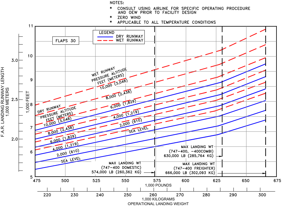
Consider also Boeing's minimum runway length official reference which states an additional 4000m will be needed to cover your heaviest mail deliveries in wet conditions (for example, two consecutive rainy days with a bout of Amazon shopping). https://static1.simpleflyingimages.com/wordpress/wp-content/...
The article says he wanted the gates to be configurable. But yeah, seems like a missed opportunity to not familiarize with the 74 series. That having been said, the AVR chips are probably a lot more useful to learn as a newbie these days. Not many people using discrete logic ICs anymore :(
That having been said, the AVR chips are probably a lot more useful to learn as a newbie these days. Not many people using discrete logic ICs anymore
I dunno. I mean, there's no question that they are less widely than in their heyday. But I think there might be a surprising number of uses where they are used for some small (very small) bit of functionality where even the smallest microcontroller is overkill.
In my own experience, I had something recently where I literally needed a single AND gate to switch a transistor on or off based on whether one or both of two power rails were HIGH. A discrete 74xx chip turned out to be the simplest way to implement that.
Hey, thanks, I did not know about the "little logic" stuff until just now. I'd always looked at the 7400 series chips (or 4000 series chips) as my "goto's" for one-off individual logic gate kind of stuff.
I'd say that pretty much every schematic I've reviewed in the last few years has a handful of logic on it. Often we need to guarantee that something is off or disconnected if the CPU fails or software crashed, etc. Hard-wired logic is good for that kind of thing.
They probably would be, actually. In quantities of 1, a discrete logic chip is around 50 cents, while that microcontroller is $2.50. In higher quantities the logic gets cheaper faster. For this project, you would need:
1 quad NAND gate
1 quad NOR gate
1 quad XOR gate
1 hex inverter
The cost isn't the main thing here, though. A better reason to go with discrete logic is that the MCU also requires an entire software and hardware toolchain to create and load firmware.
Never underestimate the cost of adding nonvolatile memory to your system.
> I built two prototypes, one with an AVR128DA48, and one with the older ATmega4809 which is pin compatible, and their performance was indistinguishable. The program only uses about 1500 bytes, so an ATmega809, ATmega1609, or ATmega3209 should be fine
For the record, you could also use a much cheaper MCU like e.g. an STM32F030C6 which costs around $0.60 for a single chip and around $0.45 for 30 chips at LCSC the moment. Of course this is completely irrelevant if you build a small number of boards like here, because then you'll probably waste most time with programming the chip and you need the necessary programming connector + tools too.
It would be fun to redesign this board for the lowest manufacturing cost with machine assembly and compare it to how much more expensive it would be to use discrete logic chips.
In this case the behavior is not equivalent, I know the author said it's close but with polling the inputs I doubt it would replicate various feedback configurations faithfully.
I recently designed a board using discreet components but I replaced those chips with a single STM8 MCU because it was significantly cheaper. While designing using gates is fun, it doesn't make economical sense, even for a simple hobbyists like me.
edit: one exception is using the venerable 555, but while it's a discreet component it's not a gate.
There are a lot of arguments about why, even non-secret data connections need encryption. The first and most obvious is that not doing so immediately puts a target on the encrypted data.
By no means an expert but to me it seems like an oversight not to.
HTTPS is secure -> a bug made 2.6% of all certificates less secure -> that's why we shouldn't use HTTPS?
I'm quite confused how that holds logically. You can either argue HTTPS is fundamentally not secure or is irrelevant; or regret that there was a bug but support using HTTPS
> Devices likely to be affected by the certificate expiry are those that don’t get updated regularly, like embedded systems that are designed not to automatically update or smartphones running years-old software releases. Users running older versions of macOS 2016 and Windows XP (with Service Pack 3) are likely to face issues, along with clients dependent on OpenSSL 1.0.2 or earlier, and older PlayStations that haven’t been upgraded to newer firmware.
Still not convinced we can claim HTTPS should not be used in the general, or in this particular, case.
Why would that be the case? Every modern browser actively discourages visiting HTTP sites so I imagine a non-negligible amount of users decide not to visit the page.
Haha fair enough but I think we digress. I did get the warning when I clicked.
The point is I see no evidence why HTTP is better for viewability than HTTPS. I showed there are cases where it’s not. You showed there are cases where it’s irrelevant. But the point remains… when is it worse and is it enough to sacrifice the security benefits?
It reminds me of a similar experience I had in a museum where the experiment had you cycling to give power to a bulb. The quicker you cycled, the more power you gave to the bulb and the brighter it was. But it was based on some microcontroller and the light bulb’s brightness was not proportional to how fast you cycled. It has like 3 preprogrammed brightness. It completely failed to give kids the intuition of the physics behind the phenomenon.
Anyway, it’s probably an unfair comparison but I like having the real deal when learning or teaching.